Welcome to the Network Operating Systems Walkthrough Workshop. In this walkthrough, we will try to relay how a typical network moves data from machine to machine.
Please open GNS3 by clicking the icon on your desktop. You should see a popup once it's opened asking to name the new project. Instead, select Project Library at the top, then NetworkOS_Arista, then click OK.
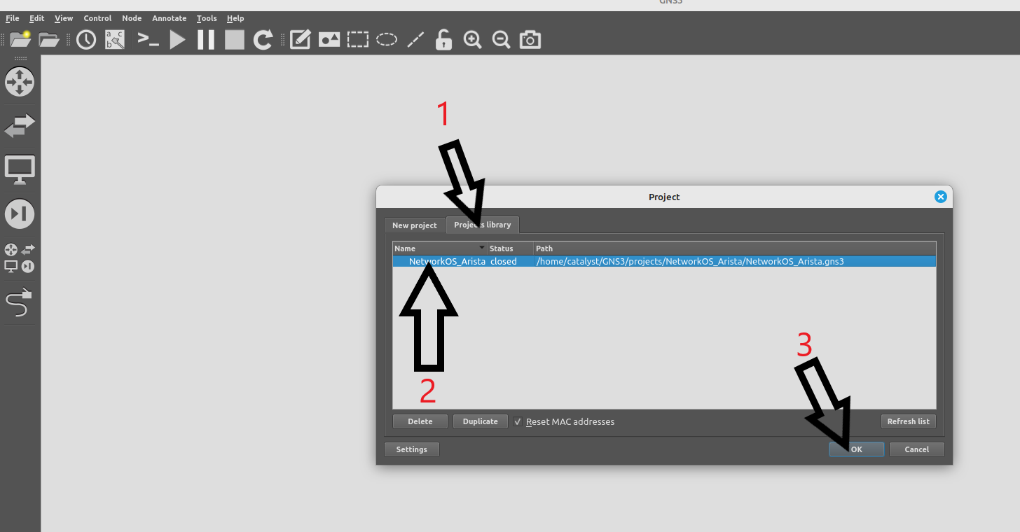
Once you click OK, the lab should load. Please take a moment to read over the lab, its devices and the connections between them.

Let's start them up! Right click on the following devices and select start:
Do not start all devices at the same time. You will freeze the computer and it will need to be reloaded.
<\WARNING>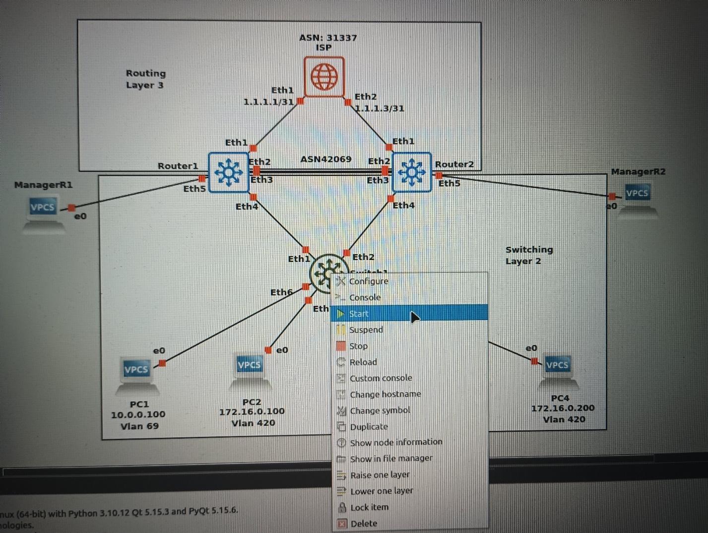
If you double-click on Switch 1, you will open a command line window. This is the terminal connection to the switch. If you see scrolling text, that is the switch booting up. When it is done, you should see a prompt that looks like this:
Switch1 login:
Enter the default login name admin and hit enter. The command line should change to:
Switch1>
This is called user mode. It is a restricted command line that allows you to run a few basic commands without making any changes to the network device. To see what those commands are, type:
?
Since we will be using this switch in a serious capacity, we will need to escalate our privilege level. The switch is in a state you'd receive it out of the box, brand new from the manufacturer, so there are no restrictions set on privilege escalations. To enter privileged mode, enter the command:
enable
The command line will change again to:
Switch1#
If you enter ? at this prompt, you'll notice a ton of new commands become available to you.
Our first task is to allow the hosts within the same VLANs to communicate with each other.
PCs 1-4 are connected on ports 6 to 9 as you can see from the main topology. To take a look at the ports available on the switch, run the command:
Switch1# show interface status
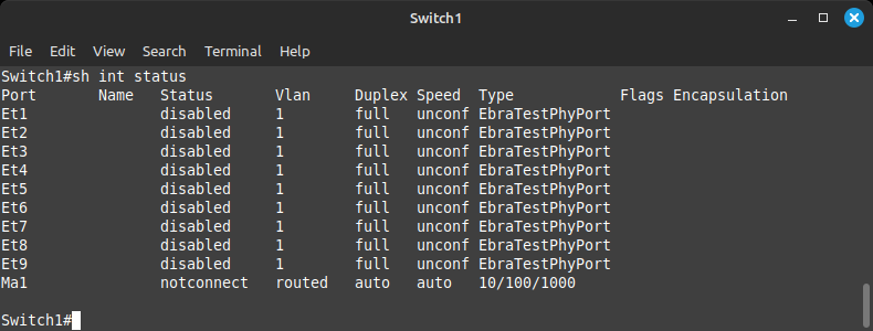
If you noticed, I was too lazy to type the word show and interface. This is allowed at the network command line as long as there are no other commands that start with the letters sh or int. The operating system will fill in those for you.
As you can see, all of the ports are disabled. Our first step is to enable them by taking the first step to configuring them. For this, you'll need to further escalate from privileged mode to configuration mode by typing:
configure terminal
Or conf t if you feel comfortable with this feature.
The command line should now read:
Switch1(config)#
The switch is now in configuration mode and will produce a different set of commands when you use the ? command.
From here, we need to move to the interface configuration mode to enable the interfaces. This is done with the command:
interface ethernet 6
The command line changes again and should now read:
Switch1(config-if-Et6)#
Since the mode has changed again, you will receive a different result when using the ? command.
All that is left is to enable the interface. This is done with the command:
no shutdown
Once you run this command, the port should come up. You can run the same command we did before to check on the ports:
show interface status
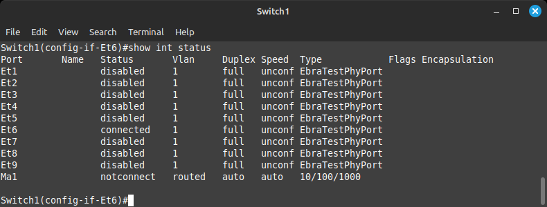
Port 6 should now have its status change to connected from disabled.
To enable the rest of the ports, there is a shortcut which will allow you to enable them all at once. You are welcome to practice the previous command on a few more or use the shortcut as follows:
interface ethernet 7-9
This command opens configuration for ports 7, 8, and 9 at the same time. Simply run the no shutdown command there and use show interface status to confirm ports 6 to 9 are up.
[Deep Breath of Relief]
Now, the hosts are configured for you as shown in the topology map. The individual ports now need to be put into their respective rooms (VLANs) so they can talk to the correct PCs.
The command to assign a VLAN to an interface is:
switchport access vlan #
Example:
switchport access vlan 69
You can go into each interface individually to assign the VLAN number as per the topology, or use the shortcut to configure ports in groups such as:
interface ethernet 6,8
For VLAN 69
and
interface ethernet 7,9
For VLAN 420
When you first assign a VLAN number that was not previously configured, the switch will create that VLAN for you. To view all the VLANs you have created and the ports assigned to them, run the command:
show vlan
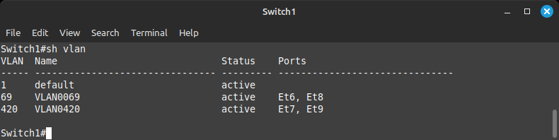
Your output should reflect the above screenshot.
Now that the ports are in the correct VLANs, PC1 and PC3 should be able to talk to each other, the same as PC2 and PC4. Double-click on PC1 on the main topology—this should open a command line connection to PC1.
This is a basic computer which allows us to test our network connectivity from point to point. If you type the command show, it will output its IP address along with its gateway and MAC address. We are interested in its IP address which is on the same network as PC3.
To test connectivity to PC3, we will use the ping command, which is an echo/echo reply utility. If the other side is reachable, we will receive an echo reply. To test connectivity to PC3, use the command:
ping 10.0.0.200
If the ports have been set up correctly, your output should look like this:
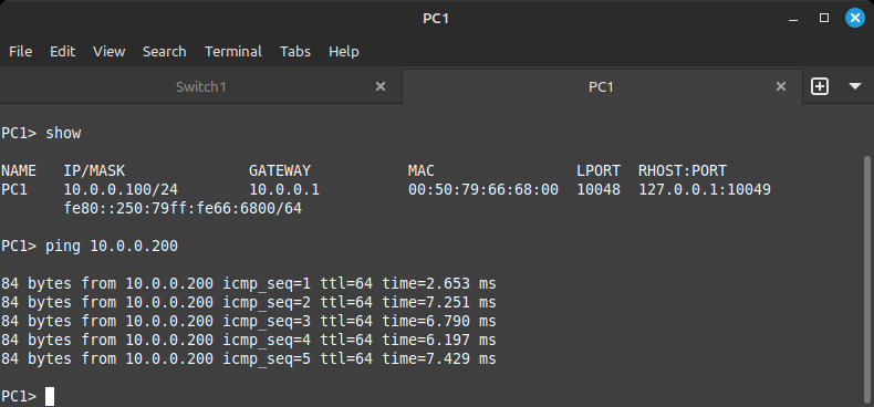
There are 5 echo request attempts per command execution and in this case, 5 echo replies, complete with source address, sequence number (order in which they were sent), TTL (time to live), and the time it took to return to PC1.
Alternatively, if you try to contact PC2, which is not in the PC1 VLAN, you'll receive an error that looks like:
Host (10.0.0.1) not reachable
This is because PC1 will try to yell to PC2, but since they are not in the same room, no one will reply. When this happens, PC1 defaults to its default gateway, which is where a PC will send its traffic when it doesn't know how to get to it on its own. Think of the default gateway as the door to the room. We haven't created a door yet, so it is unreachable!
For this section of the walkthrough, please start Router 1 and Router 2 on your main topology.
The routers are similarly configured to the switches. Simply enter the username admin at the login prompt and hit enter.
Once you enter enable mode on these devices, let's move on to building some doors for our separate rooms we created for PCs 1 through 4.
We begin on Switch1 where VLANs 69 and 420 currently live. We will need to transmit those VLANs to Router1 and Router2 to allow them to begin routing the data between them vs just switching, which doesn't use the PCs' IP addresses.
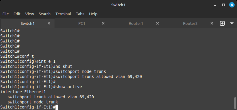
On Switch1 we will need to create Trunk links which carry VLANs 69 and 420 to Router1 and Router2. As per the topology, ethernet 1 and 2 connect to Router1 and Router2.
Enter configuration mode (conf t) followed by interface configuration mode (interface e1-2). Turn on the ports:
no shut
Instead of an access port, as is used for end user devices like computers, printers and servers, we will be using a Trunk port which connects network devices to relay their VLANs to the neighboring device. We do this by issuing the interface command:
switchport mode trunk
This sets the port as a trunk port and tells the spanning-tree protocol that it can negotiate over this port with the neighbor about which VLANs it can transmit.
To allow the correct VLANs over this port and nothing else, we issue the command:
switchport trunk allowed vlan 69,420
This permits the two VLANs to be shared over this link with the neighbor.
At any time inside the interface configuration, you can issue the show active command to see what you have already configured for the interface.
Once completed, you can confirm your configuration by issuing the command:
show interface trunk
This will show which interfaces have been configured to trunk as well as the allowed VLANs on them.
Moving on to the routers, please take a look at the topology to note which interfaces the routers use to connect to the switch as well as each other.
We will be configuring interface Ethernet 4 on both routers facing the switch and interface Ethernet 3 on both routers facing each other.
On the routers, go into interface configuration mode for interfaces Ethernet 3 and 4, then configure exactly the same way that we did on the switch.
One small difference to consider between the routers and the switch: the routers won't create the VLAN for you like the switch when configuring the PC ports.
You will need to run the command from configuration mode as follows:
Router1
configure terminal
vlan 69
vlan 420
Router2
vlan 69
vlan 420
Once you run those commands, the VLANs should appear in the output of show vlan.
I've mentioned how to get into the configuration mode and interface mode, however nothing on how to get out of them. To exit a mode, simply type:
exit
To exit all modes and return to the privileged mode command line (Router1#), run the command:
end
Now that all ports have been brought up and configured, the three devices (Switch1, Router1, Router2) will form a spanning tree for the VLANs we configured.
Without spanning-tree, packets will circle forever between the three devices in an infinite loop, creating a broadcast storm. Spanning tree will automatically disable one of the links to prevent this from happening. The command to take a look at this process is:
show spanning-tree
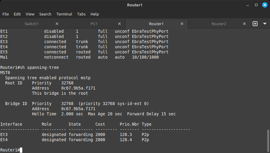
The devices running spanning tree elect a root for the tree and branch out around it. The branches furthest away from the root but still physically connected will be pruned from the tree to prevent a loop.
The blocked port is labeled as Alternate while the port facing the device elected as root will be labeled as Root. Any other active port will be labeled as Designated. Try to figure out which devices ended up playing which roles based on the output of the show spanning-tree command.
Now that we've extended our rooms to the routers, let's build some doorways for those rooms. This is where switching starts to intersect with routing. The introduction of IP addresses.
We will be creating a virtual interface for our switched VLANs aptly named a Switched Virtual Interface. To create the switched virtual interface, run the following command from configuration mode on Router1 and Router2:
Router1
interface vlan 69
ip address 10.0.0.2/24
The /24 at the end signifies the size of the network. In this case, 256 addresses ranging from 10.0.0.0 to 10.0.0.255. For a deeper understanding of address assignment, please search the web for "subnetting" at your leisure.
On Router2, we will assign the following address for VLAN 69:
interface vlan 69
ip address 10.0.0.3/24
Similarly, on Router1 for VLAN 420:
interface vlan 420
ip address 172.16.0.2/24
And on Router2 for VLAN 420:
interface vlan 420
ip address 172.16.0.3/24
If this was done correctly, you should now be able to ping these addresses from within their VLANs.
These addresses provide exit points within the routers for PCs 1 through 4. However, these PCs still cannot ping each other since their default gateways do not match with these addresses. Up next, we'll configure the default gateway addresses in such a way as to be fault tolerant in the event a link or router goes down.
To create the default gateway addresses the PCs need to communicate with other VLANs, we will create a virtual address within our virtual switched interfaces. This address will be shared between the two routers so that a fault on one router will not affect connectivity from the PCs.
The feature we will be using here is a protocol called VRRP or Virtual Router Redundancy Protocol. To configure this protocol on our switched VLAN interfaces, we first go to the individual VLAN interface and run the command in the following format:
vrrp <virtual router id> ip <virtual shared ip address>
We also set a priority to determine which router is primary and which is secondary:
vrrp <virtual router id> priority <1 - 254>
To configure this, on Router1, we will run the following commands:
configure terminal
interface vlan 69
vrrp 69 ip 10.0.0.1
vrrp 69 priority 254
interface vlan 420
vrrp 200 ip 172.16.0.1
vrrp 200 priority 254
You will notice that the virtual router id for VLAN 420 does not match up to the VLAN number, unlike for VLAN 69. This is because there is a maximum of 255 virtual router IDs, so we had to choose another number.
And for Router2:
configure terminal
interface vlan 69
vrrp 69 ip 10.0.0.1
vrrp 69 priority 200
interface vlan 420
vrrp 200 ip 172.16.0.1
vrrp 200 priority 200
Note that we set priority for Router1's VLANs to be 254 while Router2's VLANs are 200. With VRRP, the highest priority becomes the primary in VRRP negotiation. We use the VRRP virtual router ID to be 200 for VLAN 420 since the VRRP IDs only go up to 255!
To check the status of VRRP, use the command:
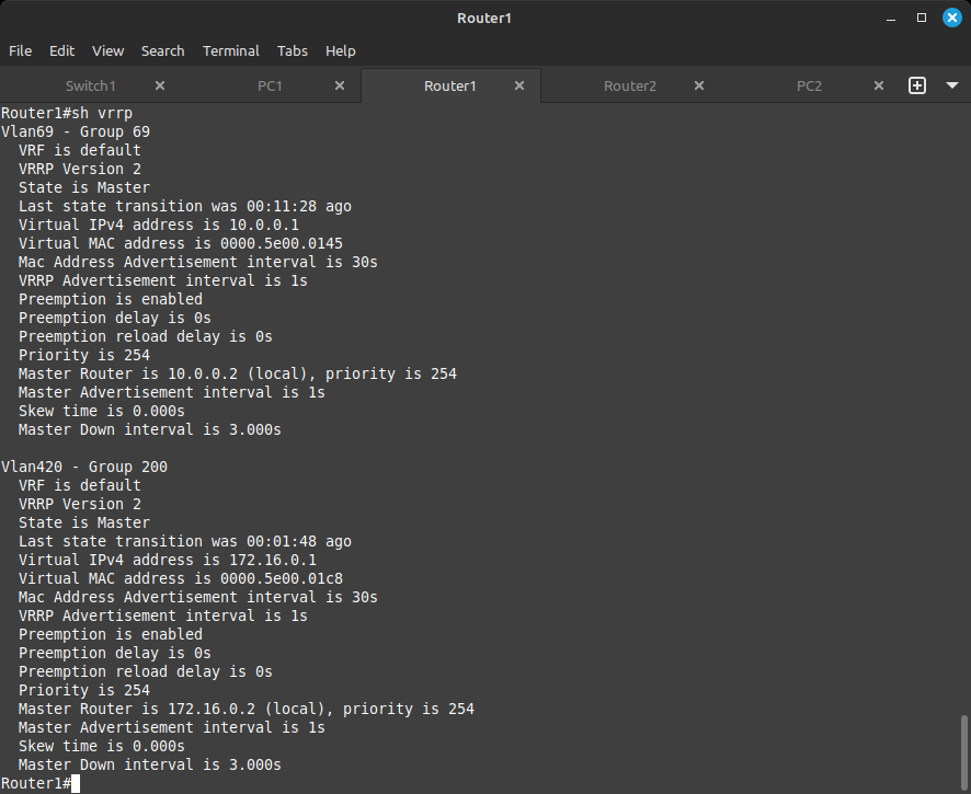
show vrrp
Your output should look like this for Router1:
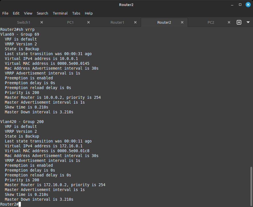
And like this for Router2:
As a final test, all your PCs should now be able to ping each other, the default gateways 10.0.0.1 and 172.16.0.1, and any address we have previously configured.
To simulate a router failure, go into Router1 and run the following commands:
configure terminal
interface vlan 420
shutdown
interface vlan 69
shutdown
All the PCs should still be able to ping each other, their gateways, and any address in the network. If the PCs still cannot ping each other, right-click on them and select stop, then start to refresh the VPCS session.
This completes the switching section of the walkthrough!
To begin, a little cleanup. Please right-click and select STOP on Switch1, PC1, PC2, PC3, and PC4.
Next, let's start up the ISP router and the VPCS ManagerR1 and ManagerR2 (right-click + start).
In the previous section we simulated how end user devices connect to a company's main network. In this section we will simulate how a company's main network will connect to the internet.
As you may have guessed, the ISP router is here to simulate the internet connection being handed off to our on-site routers.
In routing, there are no broadcasts. Every message sent must have a source and destination IP address, just like a letter going through the postal system.
To see what IPs are assigned to which interfaces, use the following command on Router1 and Router2:
show ip interface brief
Your output should look similar to this. Please note your output will contain interfaces from previous challenges. Do not be alarmed.
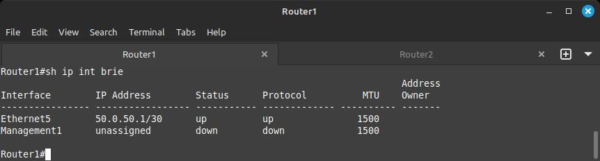
The IP address is manually configured for you. On the other side of the Ethernet5 link lives ManagerR1, which is a VPCS computer with its default gateway set to the router side of the interface, 50.0.50.1.
Please feel free to take a moment to open a command line to ManagerR1 and ping 50.0.50.1 to ensure the computer can ping its default gateway.
On the other side of our topology, we have Router2 with ManagerR2 similarly configured, but with the IP 50.0.0.1 on Ethernet5 and 50.0.0.2 on ManagerR2.
Our task is how to get these two hosts to be able to ping each other without resorting to VLANs or virtual VLAN interfaces.
The answer here is to route the 50.0.50.0/30 network and 50.0.0.0/30 network to the neighboring router, so that when the connected PCs request these networks, the routers will know where to send them.
If you look at the topology view, we previously configured Ethernet3 on each router for switching. Now above that is Ethernet2; we will be configuring these on each router for routing.
We will be assigning the IPs as follows:
This is done with the following commands for Router1:
configure terminal
interface ethernet 2
no shutdown
no switchport !this tells the device this port is not for switching, so therefore it is for routing!
ip address 192.168.0.1/30
If you run the command show ip interface brief, you should now be able to see this address assigned to the interface!
Please try to configure Router2 on your own before scrolling down.

On Router2, you should have the following:
configure terminal
interface ethernet 2
no shutdown
no switchport
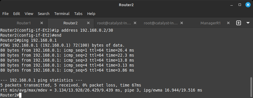
ip address 192.168.0.2/30
Please check your work with the show ip interface brief command.
NOW... Since both routers have an IP address facing each other, they can now talk to each other. You can run the ping command from these routers same as from the PCs to check on the neighboring device.
In order to share routes between routers, we will need to configure a routing protocol that will enable us to share routes between routers automatically. For this walkthrough we will be using OSPF (Open Shortest Path First) protocol.
To configure, run the following commands on Router1 and Router2:
configure terminal
router ospf 1
network 192.168.0.0/30 area 0
The router ospf 1 command takes you to the router configuration of OSPF. The 1 is just a process ID number and is irrelevant for this walkthrough... but you do have to pick a number. The network command selects which networks and ports participate in the routing protocol.
It may take a few seconds, but if you run the command show ip ospf neighbor, you should be able to see the neighboring router forming a relationship with the one you are throwing commands at.
As pictured above, if you run the command a few times, you can see the relationship establishing under the state column.
To run the previously entered command, simply hit the up arrow and it will appear. Hit enter to run it.
So how about those ManagerR1 and ManagerR2 routes? Enter the command show ip route on Router1 and Router2 to see the routing table.
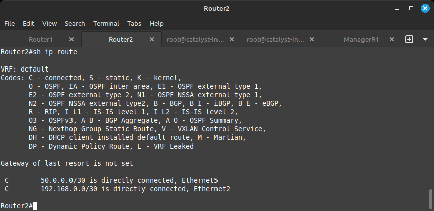
Your output likely looks like the one above. The router knows about the networks that are connected to it as denoted by the C to the far left of the network, but it's not receiving any networks yet from its neighbor. To advertise the network, we need to put in the correct network statement under the router ospf 1 configuration.
For Router1, this would be:
configure terminal
router ospf 1
network 50.0.50.0/30 area 0
For Router2, this would be:
configure terminal
router ospf 1
network 50.0.0.0/30 area 0
Now, when you run the show ip route command, you should see something extra:
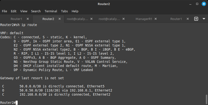
The 50.0.50.0/30 network is now visible. To the left of it, you see an O, which means the network was learned via OSPF.
You should now be able to ping between the ManagerR1 and ManagerR2 machines.
In the previous stage we used OSPF to route networks. This protocol is commonly used within an organization. When peering to an Internet Service Provider or another corporation, BGP is used most often.
BGP (Border Gateway Protocol) is a standard exterior gateway protocol created to exchange routing and reachability information among autonomous systems on the Internet.
Please note the ASN (Autonomous System Number) above the ISP router and above the links between Router1 and Router2.
But first, just like in any routing scenario, you need to configure the ports facing the ISP with the correct addresses.
For Router1:
configure terminal
interface ethernet 1
no shutdown
no switchport
ip address 1.1.1.0/31
For Router2:
configure terminal
interface ethernet 1
no shutdown
no switchport
ip address 1.1.1.2/31
If you have done this correctly, you should be able to ping the ISP router over these links. From Router1, ping 1.1.1.1 and from Router2, ping 1.1.1.3.
To configure BGP, we will do something similar but different to the OSPF configuration. Please enter the commands as follows on Router1:
configure terminal
router bgp 42069
neighbor 1.1.1.1 remote-as 31337
network 50.0.50.0/30
When you enter the router bgp 42069 command, you are defining your local autonomous system. To learn more about autonomous systems, please visit:
https://www.arin.net/resources/guide/asn/
Unlike OSPF, in BGP we don't automatically discover our neighbors based on the networks you define, but based on the specific neighbors you define. Otherwise, someone could automatically peer to your corporation and inject their own routes!
The neighbor 1.1.1.1 remote-as 31337 command defines the address of the neighbor as well as the neighbor's autonomous system.
Finally, the network 50.0.50.0/30 command defines the networks which are to be shared across the BGP relationship.
Assuming everything was entered correctly, you should be able to see the routes coming in from the ISP.
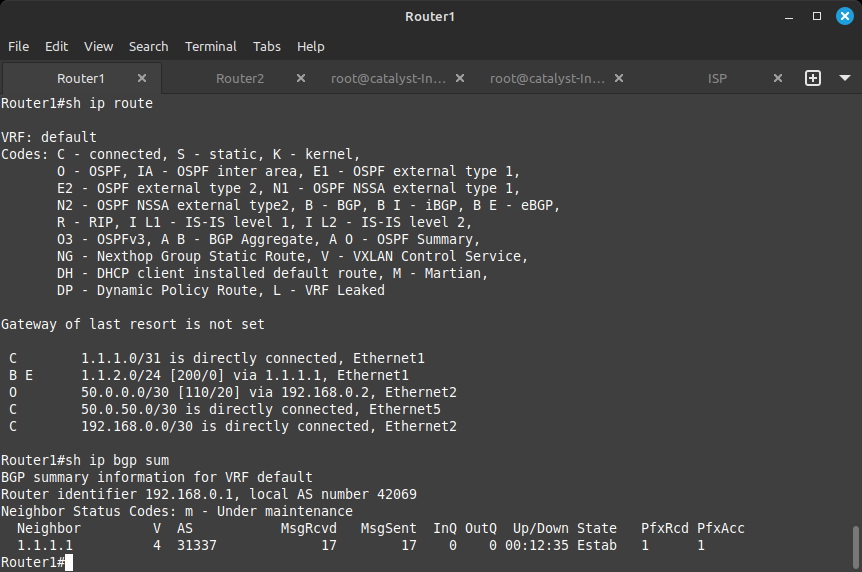
The route will have a B and an E next to it, denoting the BGP protocol and that it's an External route as it is coming from a different autonomous system.
As in the above figure, if you run the command show ip bgp summary, you will see the BGP relationship established between the ISP and Router1.
The configuration for Router2 can be configured in a similar manner. Please try to do it yourself before looking below for the correct commands.

Without further delay, the commands for Router2:
configure terminal
router bgp 42069
neighbor 1.1.1.3 remote-as 31337
network 50.0.0.0/30
You should be able to use the same commands to confirm connectivity.
If this was done correctly, you should now be able to ping the IP 1.1.2.1 from ManagerR1 and ManagerR2 and see the route to it using the command show ip route on both routers.
Well, made it all the way here! Impressive, most impressive. Wall of Sheep NetworkOS has taught you well. You have controlled your network. Now release your search skills, only they can help you on the next step.
Configure the routing protocols to share all networks between Router1 and Router2.
Shut down one of the links from the routers to the ISP.
You have completed this stage when both ManagerR1 and ManagerR2 can ping the ISP as long as at least one link to it is active.
Please use internet search to figure out how to share BGP routes with OSPF to achieve full routing redundancy.
The force is with you, young technician, but you are not an engineer yet!